
In 2024, Leads4Pass has included a total of 495 new cisco 350-501 dumps real questions! It comprehensively summarizes the core knowledge points of “implementing core service provider network technologies”. It has been tested to be true and effective in January and February 2024, and
Year-round updates are guaranteed to be effective in real-time! You can use Leads4Pass PDF or VCE learning tools to practice 2024 New cisco 350-501 dumps real question: https://www.leads4pass.com/350-501.html. Scientific practice methods help you complete the target tasks in the shortest time.
Leads4Pass 350-501 dumps exam question format:
- Exam question serial number
- Exam questions
- Answers to exam questions
- Sharing links to the core content of exam questions (difficult questions)
- Exam question analysis (analyze each option)
Leads4Pass 350-501 dumps exam real questions online sharing
| From | Number of exam questions | Type |
| Leads4Pass | 15 | Free |
Question 1:
Refer to the exhibit.
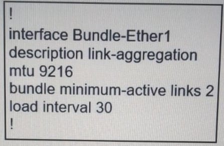
Which link aggregation configuration router is running on Cisco IOS XR software, and which LACP interface configuration is needed to add the interface to the bundle?
A. Option A
B. Option B
C. Option C
D. Option D
Correct Answer: C
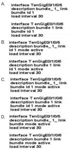
Question 2:
Refer to the exhibit.
An engineer wants to authenticate the OSPF neighbor between PE-A and PE-B using MD5.
Which command on PE-B successfully completes the configuration?
A. PE-B(config-if)#ip ospf message-digest-key 1 md5 44578611 PE-B(config-if)#ip ospf authentication null
B. PE-B(config-if)#ip ospf message-digest-key 1 md5 44578611 PE-B(config-if)#ip ospf authentication key-chain 44578611
C. PE-B(config-if)#ip ospf message-digest-key 1 md5 44568611 PE-B(config-if)#ip ospf authentication null
D. PE-B(config-if)#ip ospf message-digest-key 1 md5 44578611 PE-B(config-if)#ip ospf authentication message-digest
Correct Answer: D
Online analysis:
To configure MD5 authentication for OSPF (Open Shortest Path First) on a router interface, you need to follow these steps:
Assign an MD5 key to the interface.
Enable OSPF authentication on the interface and specify the use of message-digest (MD5) authentication.
Looking at the options provided:
- Option A suggests setting an MD5 key and then configuring OSPF authentication to null, which effectively disables authentication.
- Option B mentions configuring an MD5 key and then refers to using a key chain for OSPF authentication, which is not the correct syntax for enabling MD5 authentication in OSPF. Key chains are typically used for other protocols.
- Option C includes a typo in the MD5 key value (assuming the correct key is supposed to match the one in Option D based on consistency across options) and also sets OSPF authentication to null, which is not correct.
- Option D correctly sets the MD5 key and then enables OSPF message-digest authentication on the interface, which is the proper method for configuring MD5 authentication in OSPF.
Therefore, the correct answer is D. PE-B(config-if)#ip ospf message-digest-key 1 md5 44578611 PE-B(config-if)#ip ospf authentication message-digest.
This command sequence does the following:
‘ip ospf message-digest-key 1 md5 44578611‘: This command sets the MD5 key on the interface. The key ID is 1, and the key itself is 44578611. The same key ID and key value must be configured on both ends of the OSPF adjacency.
‘ip ospf authentication message-digest‘: This command enables OSPF authentication and specifies that message-digest (MD5) authentication is to be used. This ensures that OSPF packets are authenticated using the MD5 key configured in the previous step, which adds a layer of security to OSPF communications between the routers.
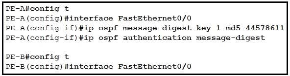
Question 3:
Refer to the exhibit.
An engineer configured multicast routing on client\’s network. What is the effect of this multicast implementation?
A. R2 floods the information about R1 throughout the multicast domain.
B. R2 is unable to share information because the IP pirn autorp listener command is missing.
C. R1 floods the information about R2 throughout the multicast domain.
D. R2 is elected as the RP for this domain.
Correct Answer: D
Online analysis:
The implementation of multicast routing in a network allows for the efficient distribution of data (such as video and audio streams) to multiple recipients without the need to send a separate copy of the data to each recipient. Multicast routing uses special IP address ranges (224.0.0.0 to 239.255.255.255) to deliver data packets to groups of hosts that are interested in receiving the specific stream of data.
Let’s break down the given options to understand their implications in the context of multicast routing:
- Options A & C: These options suggest that one router floods the information about another throughout the multicast domain. In multicast routing, information isn’t “flooded” about routers themselves in this manner. Instead, multicast routing protocols like PIM (Protocol Independent Multicast) manage multicast group memberships and build multicast distribution trees to efficiently route multicast traffic from sources to interested receivers.
- Option B: This option mentions the absence of the “IP pim authors listener” command, suggesting it’s essential for sharing information. Auto-RP is a feature that helps in the automatic distribution of RP (Rendezvous Point) information in networks running PIM-Sparse Mode. While the “ip pim autorp listener” command can enhance RP discovery in sparse-dense mode scenarios by allowing the router to listen for Auto-RP announcements, its absence doesn’t entirely prevent multicast routing from functioning. It affects how RP information is disseminated and discovered, not the basic ability to share multicast information.
- Option D: This option states that R2 is elected as the RP for the domain. The RP is a critical component in PIM-Sparse Mode multicast routing, acting as a common point in the network where multicast trees from sources meet the trees toward the receivers. The election or designation of an RP is crucial for orchestrating multicast distribution in a domain, but the statement doesn’t directly reflect the “effect” of multicast routing implementation on traffic flow or data distribution patterns.
None of the options directly describe a generic effect of implementing multicast routing on a network, such as efficient data distribution to multiple recipients. However, understanding the context and the mechanisms of multicast routing:
Option D comes closest to a tangible aspect of multicast routing setup by mentioning the election of an RP, which is indeed an important part of configuring and managing multicast routing in networks using PIM-Sparse Mode. The RP acts as a focal point for multicast group membership and can influence the efficiency and structure of multicast distribution.
So, while Option D doesn’t describe an “effect” in the traditional sense of outcomes like improved efficiency or reduced bandwidth usage, it does mention a technical aspect crucial to multicast routing’s operation. Yet, it’s essential to note that simply electing an RP does not encompass the broad range of multicast routing’s effects on a network.
Question 4:
Refer to the exhibit.
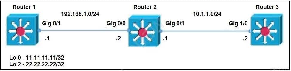
Router 1 and router 2 are running IBGP, and router 2 and router 3 are running OSPF Area 0. Router 1 is advertising loopback interfaces Lo 0 and Lo 2, and router 2 is redistributing BGP into OSPF Area 0. Which configuration must an administrator apply so that router 2 uses a route map to redistribute only the internal route from Lo 2?
A. ip prefix-list BGP-to-ospf seq 5 permit 22.22.22.22/32
router bgp 100
bgp redistribute-internal
route-map BGP-To-OSPF permit 10
match ip address prefix-list BGP-to-ospf
router ospf 1
redistribute bgp 100 metric 100 metric-type 1 subnets route-map BGP-To-OSPF
B. ip prefix-list BGP-to-ospf seq 5 permit 22.22.22.0/24
router bgp 100
bgp redistribute-static
route-map BGP-To-OSPF permit 10
match ip address prefix-list BGP-to-ospf
router ospf 1
redistribute bgp 100 metric-type 2 route-map BGP-To-OSPF
C. ip prefix-list BGP-to-ospf seq 5 permit 22.22.22.0/24
router map BGP-To-OSPF permit 10
match ip address prefix-list BGP-to-ospf
router ospf 1
redistribute bgp 100 metric 100 metric-type 1 subnet route-map BGP-To-OSPF
D. ip prefix-list BGP-to-ospf seq 5 permit 22.22.22.0/24
router map BGP-To-OSPF permit 10
match ip address prefix-list BGP-to-ospf
router ospf 1
redistribute bgp 100 route-map BGP-To-OSPF
Correct Answer: A
Online analysis:
To achieve the goal of redistributing only the internal route from Lo 2 into OSPF Area 0 using Router 2, we need to focus on identifying the specific IP address of Lo 2 and ensuring that only this route is included in the redistribution process from BGP to OSPF. The provided correct answer, A, uses a targeted approach with a prefix list, route map, and the appropriate redistribution commands to ensure that only the desired route is redistributed.
Key Components of the Correct Answer (A):
- IP Prefix-List: This is used to specify the exact network to be redistributed. The command ‘
ip prefix-list BGP-to-ospf seq 5 permit 22.22.22.22/32‘ specifically matches the IP address of Lo 2, assuming Lo 2’s IP address is 22.22.22.22 with a /32 mask, indicating a single host. This precise matching ensures that only the Lo 2 route is considered for redistribution. - BGP Configuration: Within the BGP configuration, the command ‘
bgp redistribute-internal‘ is crucial because it allows the redistribution of IBGP learned routes into OSPF. Typically, IBGP routes are not redistributed into other protocols due to BGP’s loop prevention mechanisms, but this command explicitly enables such redistribution, which is necessary in this scenario since Lo 2’s route is learned via IBGP. - Route Map: The route map ‘
BGP-To-OSPF‘ is referenced in both the BGP and OSPF configurations. It uses the prefix list to match the specific route for Lo 2. The ‘permit 10‘ statement allows routes that match the criteria set in the prefix list, effectively filtering the routes to be redistributed based on the prefix list criteria. - OSPF Redistribution: The OSPF configuration includes the command ‘
redistribute bgp 100 metric 100 metric-type 1 subnet route-map BGP-To-OSPF‘. This command initiates the redistribution of BGP routes into OSPF, but only those routes that match the criteria defined in the route map ‘BGP-To-OSPF‘. The use of ‘metric-type 1’ ensures that the redistributed routes are treated as E1 routes, which maintain the external cost across the OSPF domain, and ‘subnets‘ ensure that subnet routes are included in the redistribution.
This detailed and targeted configuration ensures that Router 2 redistributes only the route for Lo 2 from BGP into OSPF, following the guidelines provided in the correct answer (A). The combination of prefix lists, route maps, and specific redistribution commands together achieve the desired selective redistribution effect, focusing solely on the internal route from Lo 2.
Question 5:
A network administrator is planning a new network with a segment-routing architecture using a distributed control plane.
How is routing information distributed on such a network?
A. Each segment is signaled by an SR controller, but each segment makes Its own steering decisions based on SR policy.
B. Each segment is signaled by MPLS, and each segment makes steering decisions based on the routing policy pushed by BGP.
C. Each segment is signaled by an SR controller that makes the steering decisions for each node.
D. Each segment is signaled by a compatible routing protocol and each segment makes its own steering decisions based on SR policy.
Correct Answer: D
Online analysis:
In a network with a segment-routing (SR) architecture that uses a distributed control plane, routing information is distributed and decisions are made in a specific manner. Segment Routing can leverage the existing routing protocol infrastructure, such as OSPF, ISIS, or BGP, to distribute labels (segments) that are used to forward packets through the network. These segments can represent topological paths (e.g., shortest path to a destination) or specific services (e.g., a path through a firewall).
The key feature of Segment Routing is that it allows for source routing; the source of a packet can determine the entire path the packet takes through the network by specifying a list of segments in the packet header. This is done without requiring a central controller to make per-flow path decisions, which contrasts with some SDN (Software Defined Networking) paradigms that use a centralized control plane.
Given this context, the correct answer to how routing information is distributed in a segment-routing architecture with a distributed control plane is:
D. Each segment is signaled by a compatible routing protocol and each segment makes its own steering decisions based on SR policy.
This option correctly captures the essence of segment routing in a distributed control plane environment:
- Each segment is signaled by a compatible routing protocol: Segment Routing uses existing routing protocols like OSPF, ISIS, or BGP to distribute segment identifiers (SIDs) that are then used to forward packets. These protocols are extended to support the distribution of SIDs as part of their normal operation.
- Each segment makes its own steering decisions based on SR policy: While the path (or sequence of segments) can be specified by the source of the packet (based on SR policy), each node (or segment) along the path makes its own decision on how to forward the packet based on the SIDs included in the packet. This approach leverages the intelligence and flexibility of the distributed control plane, allowing for efficient and dynamic path selection while also supporting specific routing policies and traffic engineering requirements.
Therefore, option D accurately describes the process of routing information distribution and decision-making in a segment-routing network that employs a distributed control plane.
Question 6:
Refer to the exhibit.
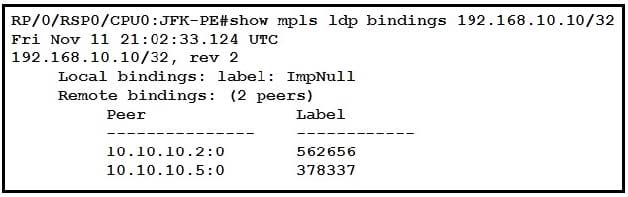
After implementing a new design for the network, a technician reviews the picture’s CLI output as part of the MOP. Which two elements describe what the technician can ascertain from the ImpNull output? (Choose two.)
A. Ultimate Hop Popping is in use for the prefix displayed.
B. Penultimate Hop hopping is in use for the prefix displayed.
C. Label 0 is used for the prefix displayed, but will not be part of the MPLS label stack for packets destined for 192.168.10.10.
D. Label 3 is in use for the prefix displayed and will be part of the MPLS label stack for packets destined for 192.168.10.10.
E. Label 0 is used for the prefix displayed and will be part of the MPLS label stack for packets destined for 192.168.10.10.
Correct Answer: AC
Implicit null is by default which means the penultimate router should only send an IP packet thus it pops the label (popping the label is known as PHP and this is done to reduce the load on the last hop router)
References: https://community.cisco.com/t5/mpls/implicit-null-and-explicit-null/td-p/1496792 https://networkzblogger.com/2017/03/21/mpls-explicit-and-implicit-null-label/
Online analysis:
The concept of Implicit Null (ImpNull) in MPLS (Multi-Protocol Label Switching) is crucial for understanding how MPLS handles label distribution and traffic engineering. ImpNull is a special label value that signifies specific actions to be taken by MPLS nodes, particularly in the context of label operations near the end of an MPLS path. When an LSR (Label Switch Router) advertises an ImpNull label for a prefix, it indicates to its upstream neighbor how to treat packets destined for that prefix as they approach the end of their MPLS path.
Given the information regarding ImpNull, let’s analyze the options provided:
A. Ultimate Hop Popping is in use for the prefix displayed.
- This is correct. When an ImpNull label is advertised, it signifies that the ultimate hop (the last router before the destination) will pop the MPLS label of the packet before forwarding it. This is done to ensure that the packet is delivered to the final destination over a non-MPLS interface in an IP format. ImpNull is essentially a directive to perform Ultimate Hop Popping.
B. Penultimate Hop hopping is in use for the prefix displayed.
- This is incorrect regarding ImpNull. Penultimate Hop Popping (PHP) is a mechanism where the penultimate router (the second-to-last router in the MPLS path) removes the MPLS label before forwarding the packet to the last router, which then routes it based on the IP header. ImpNull specifically refers to actions taken by the ultimate hop, not the penultimate hop.
C. Label 0 is used for the prefix displayed, but will not be part of the MPLS label stack for packets destined for 192.168.10.10.
- This is correct. Label 0 (ImpNull) is advertised to indicate that the ultimate hop should pop the label. Therefore, by the time the packet reaches its destination, the MPLS label (in this case, the label that would have been labeled 0) will not be part of the packet’s MPLS label stack; it would have been removed.
D. Label 3 is in use for the prefix displayed and will be part of the MPLS label stack for packets destined for 192.168.10.10.
- This option is not related to the ImpNull discussion directly, as it mentions “Label 3,” which doesn’t pertain to the specific action or indication of ImpNull in MPLS. The correct understanding of ImpNull does not involve Label 3 specifically.
E. Label 0 is used for the prefix displayed and will be part of the MPLS label stack for packets destined for 192.168.10.10.
This is incorrect because, as explained, the whole point of advertising ImpNull (Label 0) is to indicate that the label should be popped before the packet reaches its final destination. Therefore, Label 0 will not be part of the MPLS label stack when packets are destined to the specified IP address.
The correct answers are A and C, which accurately describe the implications of ImpNull output in an MPLS environment.
Question 7:
An engineer is implementing MPLS OAM to monitor traffic within the MPLS domain. Which action must the engineer perform to prevent packets from being forwarded beyond the service provider domain when the LSP is down?
A. Configure a private IP address as the destination address of the headend router of Cisco MPLS TE.
B. Disable IP redirects only on outbound interfaces.
C. Disable IP redirects on all ingress interfaces.
D. Implement the destination address for the LSP echo request packet in the 127.x.y.z/8 network.
Correct Answer: D
Online analysis:
In the context of MPLS Operations, Administration, and Maintenance (OAM), which is used to monitor and manage MPLS networks, ensuring that traffic does not leak out of the service provider domain if the Label Switched Path (LSP) is down is crucial for security and traffic management. To achieve this, specific configurations can be employed to prevent MPLS traffic from being incorrectly routed or forwarded.
The options provided focus on different aspects of MPLS and IP configuration, but the question centers on preventing MPLS OAM packets from being forwarded beyond the intended MPLS domain, particularly when there’s an issue with the LSP.
D. Implement the destination address for the LSP echo request packet in the 127.x.y.z/8 network.
This option is the correct action to prevent MPLS OAM packets from being forwarded outside the service provider domain when an LSP is down. Here’s why:
- MPLS OAM uses LSP echo requests to verify the integrity and availability of LSPs within the MPLS domain. By using a destination address within the 127.0.0.0/8 network for these echo request packets, the engineer ensures that these packets are treated as “local” to the device receiving them. The 127.0.0.0/8 address space is reserved for loopback addresses, which are not routable beyond the local host.
- Using a 127.x.y.z/8 address as the destination for LSP echo requests means that if the LSP is down and a packet cannot be properly routed within the MPLS domain, it won’t be forwarded based on standard IP routing rules outside the domain because IP routers are configured to not forward packets destined for 127.0.0.0/8 addresses out of the local host.
- This method effectively confines the scope of the echo request packets to the MPLS domain, preventing them from leaking out if there’s an issue with the LSP, thereby ensuring that these diagnostic packets do not exit the service provider’s network.
- The other options, while related to MPLS or IP forwarding behaviors, do not directly address the specific requirement of preventing LSP echo request packets from being forwarded beyond the MPLS domain when the LSP is down:
A, B, and C focus on different aspects of IP address configuration and IP redirects but do not directly ensure that MPLS OAM packets are contained within the service provider domain under the specified condition.
Therefore, the action the engineer must perform is D, implementing the destination address for the LSP echo request packet in the 127.x.y.z/8 network, to ensure these packets are confined to the local MPLS domain and are not forwarded externally.
Question 8:
Refer to the exhibit.

An engineer applied a gRPC dial-in configuration on customer\’s router to provide connection multiplexing and two-way streaming. What does this configuration accomplish in a gRPC?
A. It is the encoding requested by the gRPC server.
B. IT is the encoding that is used for dial-in and dial-out.
C. It is used for encoding with the default protocol buffers
D. It is the encoding requested by the gRPC client.
Correct Answer: D
https://www.ciscolive.com/c/dam/r/ciscolive/emea/docs/2019/pdf/BRKNMS-3537.pdf https://xrdocs.io/telemetry/tutorials/2018-03-01-everything-you-need-to-know-about-pipeline/ https://community.cisco.com/t5/service-providers-documents/implementing-grpc-telemetry-on-xr-devices/ta-p/3393966
Online analysis:
A. It is the encoding requested by the gRPC server.
- In gRPC, while servers can specify supported encodings and negotiate with clients, the dial-in configuration primarily pertains to how clients establish connections to servers. The emphasis here is on the client’s action in initiating the connection and potentially specifying the encoding as part of the communication setup. While servers do play a role in encoding negotiation, this option misplaces the focus for the scenario described.
B. It is the encoding that is used for dial-in and dial-out.
- This option broadly describes encoding usage in both dial-in (client-initiated connections to the server) and dial-out (server-initiated connections to the client) scenarios. While it’s true that encoding is a fundamental part of both types of gRPC communication, this statement does not specifically address the action accomplished by the gRPC dial-in configuration concerning encoding preferences or specifications.
C. It is used for encoding with the default protocol buffers.
- Protocol Buffers (Protobuf) are indeed the default encoding mechanism used in gRPC for serializing structured data. This option accurately reflects gRPC’s use of Protobuf but doesn’t directly address the specific aspect of encoding related to the client’s action or preference in a dial-in scenario. The focus on default encoding does not capture the specificity of the dial-in configuration’s impact on encoding choices or negotiations in the client-server interaction.
D. It is the encoding requested by the gRPC client.
- Given the clarification, this option correctly identifies the specific action accomplished by a gRPC dial-in configuration in the context of encoding. In a gRPC dial-in scenario, the client initiates the connection to the server and can specify its encoding preferences as part of the connection setup. This option directly ties the configuration action to the client’s role in requesting or specifying encoding for the communication session. It emphasizes the client’s influence in the encoding negotiation process, which is a key aspect of establishing gRPC connections, particularly when leveraging advanced features like connection multiplexing and two-way streaming.
Therefore, with the focus on the action that the gRPC dial-in configuration accomplishes in the context of encoding, D. It is the encoding requested by the gRPC client correctly reflects how this configuration enables clients to specify encoding preferences when initiating connections, thereby influencing the encoding negotiation and selection process in gRPC communications. This client-centric perspective aligns with the essential nature of dial-in configurations in gRPC, where the client’s setup actions and preferences play a critical role in the communication dynamics with the server.
Question 9:
Refer to the exhibit.
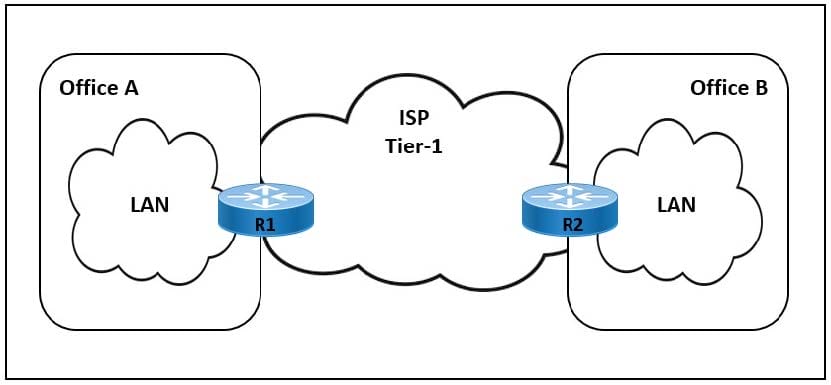
The link between Office A and Office B is running at 90% load, and occasionally the CPU on router R1 is overloaded. The company implemented QoS for business-critical applications at both offices as a temporary solution. A network engineer must update the R1 configuration to 600 ms to reduce CPU load and limit downtime after connection failure to avoid data loss. Which action meets this requirement?
A. Configure the fast-hello feature for OSPF with the command ip ospf dead-interval minimal hello-multiplier 3.
B. Configure BFD demand mode with the command bfd-demand timer 150 intervals 250 retransmit 5.
C. Configure BFD non-echo mode with the command echo interval 250 minimal 300 echo-multiplier 2.
D. Configure BFD echo mode with the command bfd interval 150 min_rx 200 multiplier 3.
Correct Answer: D
Online analysis:
When aiming to reduce CPU load and limit downtime after a connection failure, while also avoiding data loss, it’s essential to implement a solution that provides rapid failure detection without significantly increasing CPU utilization. Bidirectional Forwarding Detection (BFD) and OSPF fast-hello are both mechanisms designed to enhance network resilience by quickly detecting link or neighbor failures.
Let’s analyze each option with the given requirements in mind:
A. Configure the fast-hello feature for OSPF
The OSPF fast-hello feature can decrease the time it takes to detect a neighbor down event by sending hello packets more frequently. However, this approach can increase CPU usage on the router because it has to process hello packets more often. The command ‘ip ospf dead-interval minimal hello-multiplier 3‘ is used to configure fast hellos in OSPF, effectively reducing the dead interval to a minimal value and using the hello-multiplier to determine the frequency of hello messages. This option might not meet the requirement to reduce CPU load effectively, as sending hellos more frequently could increase CPU utilization.
B. Configure BFD demand mode
The BFD demand mode is designed to reduce the amount of control traffic sent once a BFD session is established and known to be up. The command provided does not accurately reflect BFD configuration syntax and parameters for demand mode. Demand mode can help reduce CPU usage under certain conditions, but the specified command does not align with standard configuration commands and parameters for enabling BFD demand mode.
C. Configure BFD non-echo mode
BFD non-echo mode provides a mechanism for detecting path failures without relying on the echo function, which can help in reducing CPU load since echo packets are not used. However, the command ‘echo interval 250 minimal 300 echo-multiplier 2‘ seems to misalign with the standard BFD non-echo mode configuration. Non-echo mode would typically be configured without reference to echo intervals or echo multipliers, as these parameters are associated with echo mode operation.
D. Configure BFD echo mode
BFD echo mode is designed to offload the detection of link failures to the forwarding plane, thereby reducing CPU load on the control plane. The command ‘bfd interval 150 min_rx 200 multiplier 3‘ configures BFD session parameters, including the interval at which BFD packets are sent (150 ms), the minimum receive interval (200 ms), and the detection multiplier (3). This configuration does not directly correspond to “echo mode” as described; instead, it’s a general BFD configuration that sets the desired timing parameters. This option can provide rapid failure detection with potentially less CPU impact than OSPF fast-hello, but the description of “echo mode” is somewhat misleading. BFD, in general, can meet the requirement of reducing CPU load and limiting downtime after connection failure, but the exact impact depends on the overall configuration and network design.
Given the goal is to reduce CPU load and limit downtime without specifying the exact method (OSPF vs. BFD), the options provided contain inaccuracies in the description and command syntax. For achieving the stated goal, configuring BFD (Bidirectional Forwarding Detection) would typically be the most effective approach, as it’s designed to quickly detect link failures with minimal CPU overhead. However, none of the options perfectly align with best practices or standard command syntax for configuring BFD or OSPF fast-hello features to meet the specific requirements as described. Option D is the closest to a standard BFD configuration that could meet the requirement, despite the description inaccuracies.
Question 10:
Refer to the exhibit.
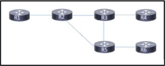
Customers report occasional forwarding issues from hosts connected to R6 to hosts connected to R1. A network engineer has just updated the MPLS configuration on the network, and a targeted LDP session has been established between R1 and R5. Which additional task must the engineer perform so that the team can identify the path from R6 to R1 in case the forwarding issues continue?
A. Configure an MPLS TE from R4 to R1 that routes through R5.
B. Implement MPLS OAM within the network.
C. Implement MPLS VPLS within the network.
D. Configure MPLS LDP Sync on each router.
Correct Answer: B
Online analysis:
To identify the path from R6 to R1 and troubleshoot occasional forwarding issues, it’s important to use tools or protocols that provide visibility into the MPLS network operation and the path that packets take across the network. Each of the provided options serves different purposes within an MPLS network:
A. Configure an MPLS TE from R4 to R1 that routes through R5.
MPLS Traffic Engineering (TE) allows for the explicit routing of traffic flows across the network, avoiding congestion and optimizing resource utilization. While MPLS TE can ensure specific paths are used (which could help in a roundabout way to identify paths), it’s primarily a solution for optimizing and managing traffic rather than for path identification or troubleshooting.
B. Implement MPLS OAM within the network.
MPLS Operations, Administration, and Maintenance (OAM) tools are designed specifically for performance monitoring and fault management in MPLS networks. MPLS OAM includes mechanisms such as LSP Ping and BFD for MPLS, which can be used to verify the LSP (Label Switched Path) between two points in the network. This makes it a suitable choice for identifying the path from R6 to R1 and diagnosing any forwarding issues that occur.
C. Implement MPLS VPLS within the network.
MPLS Virtual Private LAN Service (VPLS) is a technology that provides Ethernet-based multipoint-to-multipoint communication over MPLS networks. While VPLS can extend LAN segments over an MPLS backbone, it’s more about providing Layer 2 VPN services rather than offering tools for troubleshooting or path identification in MPLS networks.
D. Configure MPLS LDP Sync on each router.
MPLS LDP (Label Distribution Protocol) Synchronization ensures that an IGP (Interior Gateway Protocol) route is not used for forwarding until LDP has signaled label mappings for that route, preventing blackholing of traffic where LDP paths are not yet established. While important for ensuring data forwarding consistency, LDP Sync itself does not provide a mechanism for identifying or troubleshooting paths in the network.
Given the requirement to identify the path from R6 to R1 and the context of troubleshooting forwarding issues, Option B, Implementing MPLS OAM within the network, is the most appropriate action. MPLS OAM provides the necessary tools for path identification and can help diagnose any issues that might be affecting forwarding performance within the MPLS network.
Question 11:
Refer to the exhibit.
ISP ASN 65100 provides internet services to router CE-1 and receives customer prefix 198.18 18.0/24 via EBGP. An administrator for the ISP Is now provisioning RTBH services to provide on-demand data-plane security for the customer’s IP space.
Which route-map configuration must the administrator apply to router RTBH-1 to complete the implementation of RTBH services to CE-1?
A. route-map RTBH-CUSTOMER-IN permit 10description AS65001match ip address prefix-list AS65001-PREFIXESmatch community 99set local-preference 200set community no-export additives ip next-hop 192.168.255.255
route-map RTBH-CUSTOMER-IN deny 65535
description DEFAULT DENY
B. route-map RTBH-CUSTOMER-IN permit 10description AS65001
match ip address prefix-list AS65001-PREFIXES
match community 99
set local-preference 200
set community local as additive
set ip next-hop 192.168.255.255
route-map RTBH-CUSTOMER-IN deny 65535
description DEFAULT DENY
C. route-map RTBH-CUSTOMER-IN permit 10description AS65001match ip address prefix-list AS65001-PREFIXESmatch community 99set local-preference 200set community no-advertise additives ip next-hop local-address
route-map RTBH-CUSTOMER-IN deny 65535
description DEFAULT DENY
D. route-map RTBH-CUSTOMER-IN permit 10description AS65001match ip address prefix-list AS65001-PREFIXESmatch community 99set local-preference 200set community no-advertise additives ip next-hop 192.168.255.255
route-map RTBH-CUSTOMER-IN deny 65535
description DEFAULT DENY
Correct Answer: A
Online analysis:
A. Community No-Export and Specific Next-Hop
- Description and Match Criteria: Begins with a general description and matches IP addresses based on a prefix list, along with matching a specific community (99).
- Set Actions: Sets the local preference to 200, which is a common practice to prefer certain routes over others within an AS. It applies to the “no-export” community, which prevents the route from being advertised outside the AS. This is crucial in RTBH implementations to ensure that blackholed traffic does not leave the AS. The configuration sets the next-hop IP address to 192.168.255.255, a designated black hole address where traffic can be discarded.
- Effectiveness for RTBH: This configuration effectively targets traffic for blackholing by changing its next-hop to a specific discard route and ensures that these routes are not exported outside the AS, meeting the requirements for RTBH.
Given this analysis, Option A directly aligns with the RTBH implementation goals by ensuring that tagged traffic is rerouted to a null destination within the ISP’s domain and that such routing information is kept local to the AS, aligning with the requirements for on-demand data-plane security.
B. Community Local-AS and Specific Next-Hop
This option sets the community to “local-as,” which does not serve the specific needs of RTBH because it affects how routes are advertised within the local AS but does not necessarily control traffic destined for a black hole.
C. No-Advertise Community and Local Address
Setting the next hop to “local-address” might not directly correspond to typical RTBH configurations, where a specific, predefined black hole address is used to ensure that traffic is explicitly dropped.
D. No-Advertise Community and Specific Next-Hop
Similar to Option C, this configuration uses the “no-advertise” community, which helps keep the route local. However, the absence of the “no-export” community makes it slightly less aligned with the specific RTBH configuration practices that aim to prevent the export of blackholed routes.
Considering the correct answer is A, it’s clear that this option is specifically designed to meet the RTBH service requirements by using the “no-export” community to prevent the propagation of blackholed routes outside the AS and by directing traffic to a predetermined null route (192.168.255.255) for effective mitigation of unwanted traffic. This ensures that the ISP can provide on-demand data-plane security for the customer’s IP space without affecting the broader BGP routing table visibility outside the AS.
Question 12:
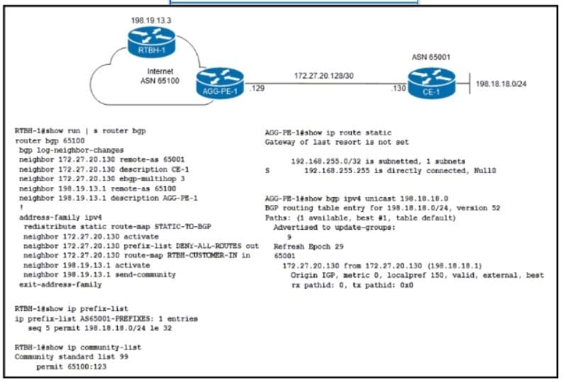
A network engineer must implement SNMPv2 with these parameters
1.
Enable SNMP community string C1sc0 with read-only permissions.
2.
Enable interface index persistence.
3.
Restrict the SNMP community to only the monitoring server with IP address 198.18 19 100/32.
4.
Provide view-only access to ospflfEntry and ospfNbrEntry.
Which configuration must the engineer apply?
A. Option A
B. Option B
C. Option C
D. Option D
Correct Answer: A
Question 13:
Refer to the exhibit.
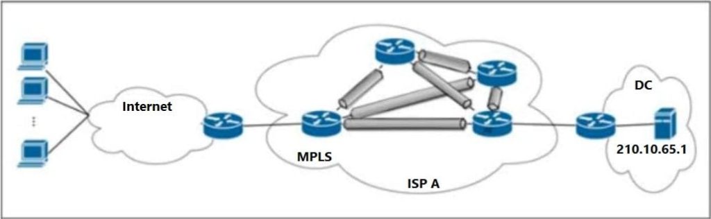
ISP A provides VPLS services and DDoS protection to Company XYZ to connect their branches across the North American and European regions. The uplink from the data center to the ISP is 100 Mbps. The Company XYZ security team asked the ISP to redirect ICMP echo requests, which are currently going to the web server, to a new local security appliance. Which configuration must an ISP engineer apply to router R2 to redirect the ICMP traffic?
A. class-map type traffic match-all B_210.10.65.1match destination-address ipv4 210.10.65.1match protocol 7match ipv4 icmp-type 3
B. class-map type traffic match-all B_210.10.65.1match destination-address ipv4 210.10.65.1match protocol 1match ipv4 icmp-type 8
C. class-map type traffic match-all B_210.10.65.1match destination-address ipv4 210.10.65.1match protocol 3match ipv4 icmp-type 5
D. class-map type traffic match-all B_210.10.65.1match destination-address ipv4 210.10.65.1match protocol 6match ipv4 icmp-type 9
Correct Answer: B
Online analysis:
To redirect ICMP echo requests to a new local security appliance, the ISP engineer needs to identify ICMP echo request packets and then apply a policy to redirect these packets to the new destination. ICMP echo requests are identified by the ICMP type 8.
Let’s break down the options based on the criteria specified in the question:
A. Incorrect Configuration
- This option attempts to match destination address ‘
210.10.65.1‘ and protocol 7, which is typically associated with the Echo protocol on the application layer, not ICMP on the network layer. Additionally, ‘match ipv4 icmp-type 3‘ targets destination unreachable messages, not echo requests.
B. Correct Configuration
This option correctly identifies the target traffic:
- ‘
match destination-address ipv4 210.10.65.1‘: Matches packets destined for the IP address ‘210.10.65.1‘, which is the web server’s IP. - ‘
match protocol 1‘: Correctly identifies ICMP packets. Protocol 1 is ICMP in the IP protocol field. - ‘
match ipv4 icmp-type 8‘: Specifically targets ICMP echo request messages, which is exactly what needs to be redirected.
Given the goal to redirect ICMP echo requests (‘type 8‘), this configuration correctly identifies the desired traffic.
C. Incorrect Configuration
- This configuration uses ‘
match protocol 3‘, which does not correspond to ICMP. ICMP is identified by protocol number 1 in the IP header. ‘match ipv4 ICMP-type 5‘ is looking for redirect messages, not echo requests.
D. Incorrect Configuration
- This option uses ‘
match protocol 6‘, which corresponds to TCP, not ICMP. Additionally, ‘match ipv4 icmp-type 9‘ targets router advertisement messages, which is unrelated to the goal of redirecting echo requests.
Therefore, the correct configuration the ISP engineer must apply to router R2 to redirect the ICMP echo request traffic to a new local security appliance is Option B. This option accurately targets ICMP echo request packets destined for the specified web server and would be part of a larger policy to then redirect these identified packets to the desired new destination.
Question 14:
What causes multicast traffic to permanently stay on the shared tree and not switch to the source tree?
A. The SPT threshold is set to infinity.
B. The RP IP address is configured incorrectly.
C. The RP announcements are being filtered.
D. SSM range is being used.
Correct Answer: A
https://www.cisco.com/c/en/us/td/docs/ios/solutions_docs/ip_multicast/White_papers/mcst_ ovr.html
Online analysis:
Multicast traffic can be forwarded through a network using different types of trees, primarily the shared tree (Rendezvous Point Tree, RPT) and the source tree (Shortest Path Tree, SPT). The choice between using a shared tree and switching to a source tree can be influenced by several factors:
A. The SPT threshold is set to infinity.
This is the correct reason that would cause multicast traffic to stay on the shared tree and not switch to the source tree. The SPT threshold determines the data rate above which the multicast router will switch from the RPT to the SPT for a specific multicast group. If this threshold is set to infinity, it effectively disables the switch to the SPT, because the traffic rate will never reach infinity. As a result, traffic will always stay on the shared tree.
B. The RP IP address is configured incorrectly.
An incorrectly configured RP IP address can cause issues with the formation of the multicast tree itself but would not specifically cause traffic to stay on the shared tree permanently. If the RP address is incorrect, the multicast group might not even be reachable or functional, depending on how the incorrect configuration impacts the network.
C. The RP announcements are being filtered.
Filtering RP announcements can disrupt the discovery and operation of the Rendezvous Point, potentially affecting the establishment of the shared tree. However, this would more likely lead to issues in forming or maintaining the multicast distribution tree, rather than causing traffic to stay on the shared tree indefinitely.
D. SSM range is being used.
Source-specific multicast (SSM) is a method of delivering multicast traffic where receivers explicitly join the multicast group from specific sources. SSM uses only source trees (SPTs) and does not use a shared tree or an RP. Therefore, if SSM is being used, the concept of switching from a shared tree to a source tree does not apply.
Given these explanations, A. The SPT threshold is set to infinity is the correct cause for multicast traffic permanently staying on the shared tree and not switching to the source tree.
Question 15:
DRAG DROP
Drag and drop the descriptions from the left onto the corresponding OS types on the right.
Select and Place:
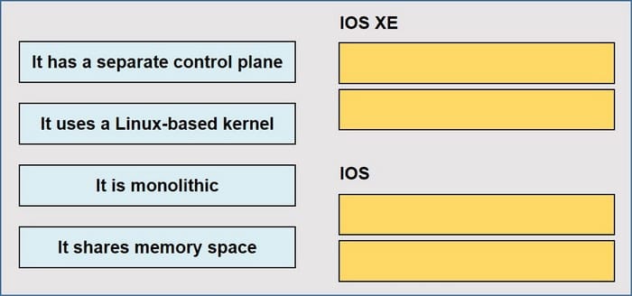
Correct Answer:
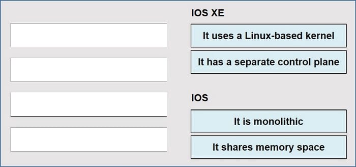
IOS XE: It uses Linux-based kernel It has a separate control plane IOS: It is monolithic It shares memory space
In conclusion:
Download Leads4Pass new cisco 350-501 dumps real question: https://www.leads4pass.com/350-501.html, use PDF or VCE tools to help you practice scientific tests to ensure that you successfully pass the 350-501 SPCOR certification exam